Monday, February 28, 2011

Week 31 Feb. 21-26, 2011

Last week I spent most of my time working on hairsprings. I hadn't touched any since before the christmas break so it had been a while. But that was the last part to get the W-01 running so I had to get started.

The first part was to attach the inner part of the spring to a collet. Then you center and flatten the spring to the collet. After that you use the vibration tool to find the vibrating point. It looks like a complicated tool but it's not too crazy. The idea is to pinch the spring at the correct length to make your balance wheel oscillate at the same speed as one of a known frequency. This will ensure your balance will be the right frequency to match the gear ratios of the rest of the watch. In the picture you can see an 18,000 on the side which corresponds to 18,000 vibrations per hour.

Finding the vibrating point is also used to see where you need the spring to come out of the collet (for flat hairsprings). This is because the rate at lower amplitudes changes depending on the angle of the colleting point to the vibrating point. Hopefully this makes sense. If not maybe I should work on that, might have to explain this on a test at some point...


Here you can see the wheels are meant to have the spokes aligned so you can see by eye if the wheels are oscillating together.


As I said before, the W-01 will have a Breguet overcoil. So after I was done finding the vibrating point, I was ready to bend the overcoil. The idea is to make two 35-45° bends to make the last coil higher than the rest. Then you bend the spring into a certain shape according to the diameter you want at the pinning point (end of spring where the clamp pinches it).

I showed a picture of the different overcoil shapes last week, here it is again. I originally picked the one in red, but I had to use the one in green after finding the vibrating point to be much longer than before because of the heavy balance wheel. As you can see, the lower the number, the closer to center C becomes. I had already made the clamp so I had to follow the pattern that matched the diameter of the clamp.


The overcoil was not really that difficult to bend for me. I built a little tool to help me bend the overcoil part of the spring that worked really good. It was just a really thin plate of brass that I could slide the majority of the coil under, and then just work on the overcoil part. It helped keep it much more flat and straight. But it still did take about 3-4 hours to get it looking nice and following the correct shape. You can see in the photos the last part of the spring seems to rise up a bit so I'll have to see what is causing that.


Here you can see the two bends in the spring that raise the last coil up. Then from there it goes overtop and around to where the clamp is. 


And here you can see where the clamp pinches the spring. That is the exact point I want the vibrating point to be. It will take some time and skill to get it perfect, because this is what sets the rate of the watch. even a few hundredths of a millimeter to the left or right could make the watch go 10-20 seconds faster or slower. 


There is also some extra spring sticking out on the right side that I will trim off later when I know the exact location. 


So after putting the spring in the clamp the watch was ready for its first oscillation! I just wanted to see it working so I didn't clean and oil everything, but it still worked fine on the first try. It was very satisfying to see it finally come to life. It was also cool to see the overcoil as I hadn't really looked at one up close (even though we have worked on Rolex watches with overcoils, I just never really looked at it). 

Next thing I did was clean everything to see if I had a decent amplitude. We had to make the balance staff so you never know if things are going to work great on the first try. I had 290° amplitude in the horizontal position so that was a great start. The vertical position wasn't that great (215°) but there are a lot of reasons as to why. I now have to start fine tuning to get the results I am looking for. But here's a quick video of the watch actually running!


One other thing to mention about the overcoil. f you watch the video you can see how the spring expands and contracts evenly around the entire spring. This is because the overcoil places the center of gravity in the center of the balance. On a flat spring the center of gravity is not in the center of the balance so the spring will expand and contract a different amount in different spots. This is one of the benefits of the overcoil.

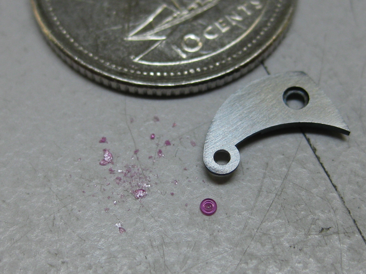
I am also working on getting the AMS1 running. It will have a flat hairspring so I will have more examples of that later. But I put in the eccentric banking pins and I think they look cool. Now I still have to adjust them and also make a spring for that balance. And I have to figure out a way to make some regulating pins. They are extremely small so it's not going to be fun...


Monday, February 21, 2011

Week 30 Feb. 14-19, 2011

Holy cow, 30 weeks doing this already. Seems like I could've accomplished a lot more. I suppose I didn't originally have a CAD program or plan to make my own mainplate so maybe it's more like 20-25 weeks realistically. But anyways here's the scoop on last week.

I actually didn't do a hell of a lot. I started the week in hopes of making the balance staffs needed for the W-01 and the AMS1. I finished one for each. I will still need to make another one for the AMS1 but for now it is fine. I will use the first one to rivet to a test balance wheel so I can do all the testing without using the nicely decorated balance wheel I plan to use.

Just to test the staff I made, I glued it to a temporary balance wheel. The staff was just the right length at the extra 0.18mm I had calculated. In these first two pics I was just testing the staff to see if the pivots fit and if it was the right length.


Not the nice balance wheel like the one with the screws...


Next I riveted the balance staff for the W-01 onto the nice balance wheel. The screws are for regulating the watch. This is also the underside of the wheel.


Next I started making the spring clamp. Usually there is a stud that holds the one end of the hairspring with either a pin or shellac. But this design is a little more solid and suits a Breguet overcoil design a little better. Note: a Breguet overcoil is just a different shape of the end of a hairspring to aid the center of gravity of the spring. Normally a hairspring only expands and contracts one way because of its shape. But the overcoil reduces this effect creating a better timing between the 6 different positions (crown up, left, right, down, dial up & down).

Here you can see different shapes of overcoils, depending on the radius of the end point. I chose the one circled in red. We have to bend the spring by hand in the air. I'm sure it won't be easy...


So anyways, the design is pretty simple for the clamp. Just a disc that has a flat face on one side, with a steel piece screwed on creating a clamp. This is the underside....


The spring will go into the spot indicated by the green arrow. Please forgive my horrific attempt to free hand draw a hairspring in photoshop hahahaha. More info on balance springs here.


I had to drill and mill holes in the bridge to fit the screws. These are some of the smallest screws I've had to make. The head is 0.60mm, thread 0.50mm and the length is only 0.80mm. The one for the clamp is really small as well. I think I will be making all the screws blue.


The end of the screws will be polished so you will just see two circles. The top of the clamp will also be flat polished.


Here you can see what it will sorta look like with the pallet fork bridge and balance wheel. Very simple design but nice I think.


I think I will try to leave the arms of the balance in this position. That way it won't block anything from view when the watch isn't running (not like that'll really matter, but still).


As for next week I will be finishing the bridges and hopefully bending the spring to get the watch working! See ya

Sunday, February 13, 2011

Week 29 Feb. 7-12, 2011

*Update: added a few photos of the barrel bridge stem cut out

This week was quite a bit worse than last week as far as getting things done. On Monday I tried to cut out the recesses for the balance bridge but it didn't go so well I ended up making another one and finally got it to work. 

I was testing the bridge with an original balance wheel and staff and as you can see the mainplate jewel is sticking out quite a bit. This just means the balance staff I make will have to be a bit longer, not a big deal.

Then I worked on the recess for the sliding and winding pinion on the barrel bridge. I didn't really have the right tool or machine to make the correct cut out on the bridge so I had to improvise. It is supposed to be a curved shaped cut out for a round piece but I just made small steps in the material to create the recess. I forgot to take a picture of it so I'll have to update this tomorrow otherwise this makes hardly any sense. But anyways, you can't see the recess so it's not a big deal what it looks like really... Here's a pic of cutting the recess for part of the winding stem out of the bridge and mainplate.


Pic of the original (left) and the AMS1 (right)


Then I had to make a winding stem since the hole in the mainplate and bridge are a bit bigger than the original one. Only took about 3 hours (compared to the 6 or so for our exam) since I didn't really need it to be nearly half as accurate. Here are a couple pictures, with a temporary crown glued on.


Next thing I had to make was a new setting lever spring. The one I had made before was nice but it wasn't quite working properly on account of the shape of the spring. It was curved the opposite way and was too strong. Also when you pulled the stem out, the pin would jump out of the notch because there wasn't a big enough rest for it. So here is the picture of the new one on the left. It all works great now and the functions are smooth.


Saturday I decided to make a few of the parts needed for the moon phase. The springs were simple to make, but I found hardening and tempering them a bit tricky. They are very thin (0.20mm) so I was worried they might become bent while hardening. I first tried to put them in this tube (pictured) with some charcoal inside but the springs didn't get hard. Then I tried pressing them between two thin plates but that didn't work either. Finally I ended up making a little basket dealy out of wire that I wrapped around a piece of steel first. Then I put one spring in at a time and that worked great. They came out still straight and finally hard. 


As for an explanation of the springs. There needs to be a spring holding the star wheel and the moon phase wheel in place when they are not being activated. It keeps the wheels from moving and also so that the finger of the cam will always activate in the same place. The photos explain best I guess so just take a look. I know, I know the teeth on the moon phase wheel are backwards. That's just the spare trial wheel and I did a trial decoration on the underside of the wheel. It is just in upside down to see the decoration....


So next week I have to get started making balance staffs. I need to make 1 for our school watch W-01. And I should make maybe 2-3 for the AMS-1 since I would like to have one for a trial balance, one for a good nicely decorated balance, and one for a spare in case I ever break one. I could make a spare for the W-01, but I figure it would be not so likely I would break a balance staff in a pocket watch that isn't used. But anyways, not looking forward to a whole week or so making balance staffs. Nicholas if you read this maybe you can make me one?? Haha, cya next week...

Sunday, February 6, 2011

Week 28 Jan. 31-Feb. 5th, 2011

This should be a lengthy update this week. I had 5/6 days go really well so lots of things to report. This was our first week back to school after the internship I did at Panerai. Our goal now in school is to get our W-01 watches running and ready for the COSC certification. We have to send the watches in at the end of February so we don't have much time.

The first thing I started with was putting in a bronze bearing on the barrel bridge for the W-01. I had already put one in on the mainplate and needed to finish the bridge. I also did the perlage to the underside of the bridge. I didn't take any pictures of that but it doesn't look much different than the other bridges. After this was complete I only have the balance staff to make and the stud holder (which doesn't have a final design yet) and the Breguet overcoil hairspring and I will have a running watch. Considering I have almost everything done (except those few small things) I got to work on my AMS1 a little bit.

A while back I had an idea that I could do Geneva stripes on the Schaublin 70. Geneva stripes (or waves) is a pattern that creates the illusion of a waved surface on the flat surfaces. It's not the most complicated to do, but if done properly it is much more difficult. The goal is to leave marks on the surface and not create big steps from one side of the stripe to the next stripe. If you look up close at even some of the expensive watches you will see big steps and it's not so nice. Here is an example of perfect geneva stripes on the Phillipe Dufour Simplicity watch. If you look at the side views of the bridge you can't see any wave in the bevel. If you look at some of the other well known brands up close you can see the quality isn't even close to this good.

So I set out to achieve something close to ideal, but accepting I might not be able to get it perfect. I figured I could use the milling attachment and with the right tool set to the right angle I could do it. So Tuesday I set out to see if I could get a good result. I only had a rough idea of how the professionals (like Phillipe Dufour, Vianney Halter and Kari Voutilainen to name a few) do it. I tried using diamond paper on some flexible plastic like I was told it was done, but I had not so good results. I tried different speeds and angles but nothing was giving me the right result. Plus this was all based on a partial guess of how it was supposed to be done.

Then I set up a stone in the milling attachment and after tweaking with the angle for quite some time and a lot of trials, I finally got something I think would be acceptable to put on my watch. Here are some pictures to show the result so far.


I also had some advice from my instructors friend Enrico (might have spelled that wrong) who used to work at Vianney Halter. So thanks to him for stopping by and giving his advice and opinions.


I had first tested everything on brass, but I figured I'd better try it on German silver since that what my bridges are made from. It's still not perfect but with a little bit of tweaking I think it will look as close as possible.

You can see from the side view that there is not much of a wave in the bevel. If you see an ETA watch up close sometime look at how deep the waves are!


The bevel is still nice and straight!


I also have to make a support for when I actually do my bridges. The bridges have to be almost perfectly flat before making the stripes and I need to support the weak part of the bridges so they do not flex and create a funny pattern. But I have a lot of other things to do before I need to worry about that...

Next thing I worked on was another design and finish aspect. As you might know I really like the design of the A. Lange & Sohne watches. One thing I really like is the engraved balance bridge. I thought if it's not too crazy expensive, I could get mine engraved. So I drew up a pattern I think is pretty cool and interesting. My instructor knows a really good engraver who might be able to do it for me. Here's her website by the way: http://gravalance.ch/. She does some really nice work, hopefully it works out!


Another thing I started working on was the dial. Since my watch is not a traditional design with the hour and minute in the center, I have to make my own dial. I tested some things out a while ago and found a really nice finish with sandblasting brass and coating it with the black rhodium. So I am trying to make my dial out of brass. Usually the dial feet are soldered onto the dial after, but I am going to try to mill them out of the full material. I think they will be a little more solid that way. Anyways, I flattened one side and then glued it to my milling block. Then I milled the feet out and also drilled the holes for the pivots, and milled out the moon phase window. Then since I left a lot of material on the other side I had to flip it over and mill the rest off. This turned out to be a not so hot idea. I am not 100% sure, but I think the aggressive action of the milling caused the dial to be warped. It is only 0.60mm thick so that doesn't help. I tried to flatten it but it just didn't work out. So now I am trying a slightly different approach, crossing my fingers it works. I don't really want to increase the thickness that much so I'll try to figure something out. But here is a picture of the underside of the dial. One good thing is that I can use this one to test the finishings on it!


After that I decided to finish an old project I started a while back. The project is a collet holder for the 8mm Schaublin collets. I had done the top part that holds the collet a long time ago but we didn't have the tap to thread the screw for the collet. We finally got it a while back so I just drilled and tapped the piece and it was done. Only an hour of work to finish it. It's a very handy tool though and will be nice to have. I guess I need to get some collets to actually use it!


Then I set out to make another (hopefully the last!) pallet fork bridge. I had the other one from the previous setup but when I put it on the mainplate I made, the jewel of the bridge was not aligned close enough with the one in the mainplate. And since I didn't want to put in a larger jewel, making a new one was the only solution. So I milled it out, hardened and tempered it and then set it up to center the hole for the jewel. And just to show how accurate you have to be when making this hole here is an explanation. The jewel is exactly 1.000mm in diameter. Depending on the material you are pushing the jewel into, the hole has to be 0.005-0.010mm smaller than the jewel diameter. With steel, it has to be about 0.005mm less. It's not that easy to measure at this dimension. I thought I had the hole to about 0.992 or 0.993mm. But when I tried to push the jewel in, it just cracked. So i had to take off another 1-2 microns of material so it would push in nicely, but not be too loose. Here you can see the difference between a few microns of material!


I now have the bridges done up to the balance.


We also got the pinions for the wheels  so I was able to rivet the 3rd and fourth wheel for the W-01, and also the 3rd wheel for the AMS1. For the 4th wheel on the AMS1 I had to do something different for the pinion. Since I added almost 1.50mm to the dial side of the mainplate, the original 4th wheel pinion wouldn't be long enough to extend through to the dial. So what I though would work was to make a longer pivot and push it onto part of the original one. The pictures show a little better what I'm talking about. It was quite a nerving experience though because I had to rivet the pinion onto the wheel first, and then push that extra piece on after. Then if it was not running straight I wouldn't have a way of removing it and the nice wheel I already beveled and plated would be unusable. But everything worked out and it runs really straight and flat. A big moment this week!


I think the wheels are quite a bit nicer now that they are beveled and plated.


Then on Saturday I set out to make the click spring and click and get them to work. First I milled out the springs (I made one extra) in the M1, then hardened and tempered them.


Here you can see how small the spring is. And it isn't just flat either, it has to extend into the click.


 Then I had to adjust slightly to make it fit into the slot I had cut out in the bridge and in the click.


And here you can see the click set in and the spring is not visible. I also had to adjust the thickness of the spring because the tension was a little bit too much at first. But now it is working great. And I think it looks pretty cool! At least much better than the original 6498 click...


And lastly here is a picture of the gear train with and without the bridges on. I think it looks pretty awesome, even without it being finished nicely yet!


Now I just have to get the balance bridge milled out. Should be close by the end of next week. Hopefully I can have more weeks like that one. I think it was the best week I have had since I started this project!